Software for Automotive Lighting Design and Analysis
An intelligent 3D CAD system for optical engineers. Bring your exterior lighting products to market ahead of your competitors.
Design automotive forward, rear and signal lighting, and reflectors

Quickly Create Reflector or Lens Geometry
Quickly and easily create reflector or lens geometry with LucidShape FunGeo. It leverages proprietary algorithms that automatically calculate and construct optical geometries based on user-defined illuminance and intensity patterns. This unique, functional approach gives you the freedom to focus on overall design objectives rather than the implementation details of complex optical components.
Produce Rapid Illumination Simulations
Accelerate LucidShape illumination simulations with GPUTrace and experience a quantum leap in speed! LucidShape is the first optical simulation software to take advantage of graphics processing unit (GPU) computing to deliver simulation speed increases by orders of magnitude compared to multithreading capabilities.
Deliver High-Speed Photorealistic Images
Use LucidShape’s Visualize Module to demonstrate luminance effects when light sources in a model are illuminated and depict all interactions between system geometry and light sources. Designers can then evaluate how a lighting system such as turn signals and brake light will be perceived by the human eye. The Visualize Module is a fast, reliable engineering tool that enables designers to perform design checks and make improvements early and often in the product development process.
Start with the Best Match
Find the best match for your design with the many modules LucidShape offers. Multiple modules can be licensed in various configurations to best match your needs.
LucidShape SmartStart Library
Save time and reduce costs with access to a library of materials and media commonly used in the design of automotive lighting systems. Includes refractive index and absorption data as well as pre-defined volume scatter and BSDF materials.
Additional Features
- Interface to Microsoft COM with LucidCOM, which allows you to develop custom solutions to automate tasks and leverage other COM-enabled tools, such as Rhino 3D or CATIA
- Perform a wide variety of design tasks through a script procedure written in a C/C++ -like language with LucidShell
- Access the LucidObject library, which holds a rich set of different object types to define geometry, material, media, motion, simulation, tasks, behavior, interactions and utility operations
- Identify the geometric origins and ray history of individual contributions to the luminance image
- For Monte Carlo ray tracing simulations, set a fixed random seed, which deactivates the randomization of ray creation and interaction
- Use the MacroFocal feature for the design of multifaceted reflectors
- Pixel Light features support the efficient design and simulation of high-resolution, dynamic pixel light headlamps
- The LucidShape human eye vision image (HEVI) capability has been extended to give designers more flexibility to control image brightness, contrast, and color shift
- Advanced Analysis Module streamlines analysis steps, provides access to a wide range of analysis tools, and simplifies interactive design analysis and troubleshooting
LucidShape: Applications
LucidShape can be applied to a wide range of applications. It consists of a powerful set of tools to simulate all kinds of light sources, surfaces, materials and sensors. See applications in:
Automotive

Reflector Design
The computer based design of automotive reflectors is a must in state-of-the-art lighting systems. LucidShape’s “functional geometry” design tool LucidFunGeo supports the design of free form reflectors for all types of automotive lighting. The design of Free Form reflectors is one of the major strengths of LucidShape. A big variety of automotive reflector types can be created and simulated:
- Automotive low beam
- Automotive high beam
- Automotive signal beam
- Automotive low beam reflector for dual filament bulbs
- Automotive high beam reflector for dual filament bulbs
- Free form source

Automotive Projector Lamp
The projector type lamp had become a widely used concept in automotive headlamp applications. LucidFunGeo supports the creation of this module in a sophisticated way. You can easily create your own module with one of the LucidFunGeo applications. The module consists of a light source, a reflector, an optional shield and a projector lens.
All parameters can be stored and reloaded at any time by the commands “Save Config” and “Load Config”. Several configurations of previously designed reflector examples can be loaded. The light source is defined as either cylindrical, rectangular, circular or as a ray file. It may also be selected from an other previously built model. A number of shields with different rims for ECE or SAE cutoff can be used.
The lens can be chosen from a wide range of different lens types, i.e. aspherical, FF fresnel, elliptical, hyperbolical, spherical, planar convex, planar concave, biconvex, biconcave, rotational, extruded, potato chip lens.

Virtual Beam Pattern
This application calculates a light source distribution “reversely” from sensors. It makes use of the method “reverse sensor light”, i.e. the light in the sensor is projected back into a virtual light source. This tool can be used for the beam pattern definition for certain driving situations like curved roads. A reverse sensor light is an intensity distribution which would be needed to illuminate a scene resulting in identical light distributions in all sensors. This application presents examples for curve, fog and low beam light.

License Plate
The license plate application can be used in regulation committees to find the right illumination. The challenge here is to find the right lamp design for a desired beam pattern.
This application creates the setup for a license plate with a lux sensor according to ECE, SAE, JIS, Brasil Contran 692/88 and Argentina 875/94 regulations. The license plate can be illuminated with one, two or three license plate lamps. Because of the small distance between the lamps and the license plate, the license plate lamps should be constructed with ray files. The actual luminance can be compared with the regulations and show whether the individual requirements for the plate dots will meet the regulations or not.
Example for a measurement:
LID name: lux sensor for plate dots
Regulation: license plate JIS
| Measure Point | Value [cd/m^2] |
Is Ok? | Min [cd/m^2] |
Max [cd/m^2] |
Position (x,y) in mm |
| P1 | 4.36 | OK | 2.5 | — | – 125,50 |
| P2 | 3.24 | OK | 2.5 | — | -25,50 |
| P3 | 3.21 | OK | 2.5 | — | 25,50 |
| P4 | 4.29 | ?? | 2.5 | — | 125,50 |
| P5 | 0.29 | ?? | 2.5 | — | 125, -50 |
| P6 | 0.30 | ?? | 2.5 | — | -25, -50 |
| P7 | 0.22 | ?? | 2.5 | — | 25,-50 |
| P8 | 0.29 | ?? | 2.5 | — | 125,-50 |
| Lmin | 1.67 | ?? | 2.5 | — | 55,0 |

Retro Reflector
Checks the retro reflection with test tables. This application creates a setup with your sample retro reflector optic, a light source and sensors. Light from the disk emitter will be reflected from the sample and measured with a sensor. The sample can be inclined in horizontal and vertical direction. Subsequently, the retro reflectance can be checked for different inclination angles according to ECE and SAE regulations.
Individual Candela sensors will be created in the setup for each inclination, e.g. by applying the simulate all button.
LEDs
The automotive lighting industry is undergoing a fundamental change in the design and development of headlamps, especially with the integration of LED applications and lenses. New features and applications within LucidShape helps you to manage new tasks and techniques with added support of LED sources and lens optics.

This graph above shows the relative luminous intensity versus the polar-angle from the vertical axis in degree for an Osram LED.
Model LEDs
LucidShape offers different possibilities to model LEDs:
- LED libraries
- Ray files
- Complex model
- Point Light Source
LED libraries
LucidShape holds a large library of Osram and Lumileds LEDs. Following types are implemented:
Osram LEDs
- 1mm LED
- 3mm LED
- 5mm LED
- Argus
- Chipled
- Firefly
- OvalLED
- SmartLED
- SMT with LENS
Each type holds different individual LEDs.
Lumileds LEDs
- Batwing
- Lambertian
- SideEmitter
Again, each type holds different individual LEDs
Ray file
The LED can also be simulated with a ray file.
Complex model
One can also picture a LED with a complex model.
LED Point Light Source Editor
You can create any arbitrary LED light intensity distribution for point light sources with the LucidShape’s LED Point Light Source Editor. The intensity can be entered in 5° steps. Optionally, one can enter different values in horizontal and in vertical direction.


Customize LEDs
You can also model your own LED. This simple model consist of a cone reflector, a spherical surface and a directional emitter, which represents a LED with Lens. The LED is either modeled with a lambert emitter on a disk (disk emitter) or on 5 planes forming a box shape (box emitter). The disk radius and the box size and the number of rays for the simulation can easily be altered within the dialog box.
LED Beacon Light
This application shows a LED ring with an outer lens for a beacon light. You can choose the number and the position of the LEDs, and the geometry of the outer lens. The optical contours of the lenses can either be of type elliptical, hyperbolical, FF inner and FF outer. The lens radii, lens height, focus radii, sweep angles can also be altered.
After the simulate button is pressed, one can see the light intensity distribution with a Candela sensor.
Lightpipes

Light Sign
This is an example for a light sign design. It consists of a cylinder light source in a reflector, a light pipe leading the light into a funnel reflector which leads the light into a light sign display. This light sign creates the characters EXIT in the light intensity distribution.

A section of the light sign example with random rays.

The light intensity distribution from the example above. The simulation is performed with a Monte-Carlo ray trace with 300.000 rays.
Light and Motion
Light Sign
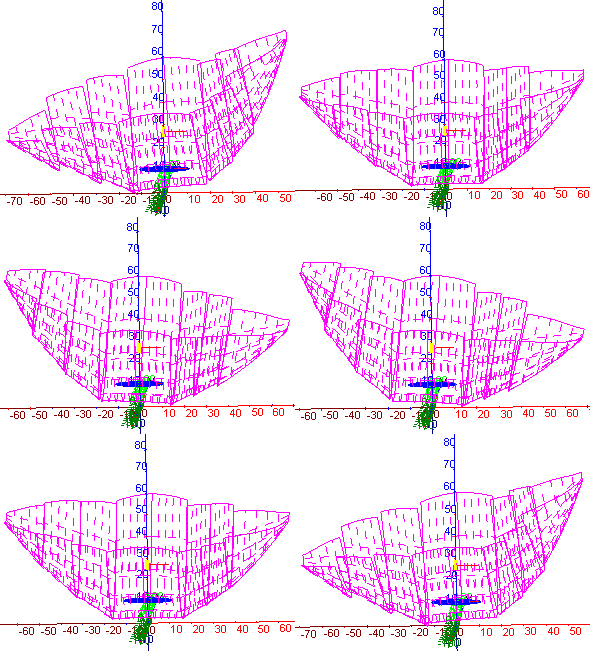
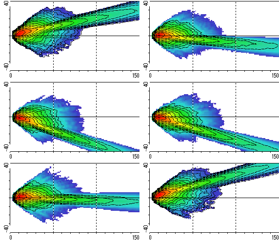
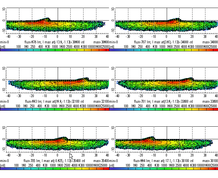
This is an example for a light & motion simulation. A possible application might be a future low beam curve light. Individual pairs of facets can be rotated about a user defined point by a user defined angle and range. Even the animation interval can be defined in the dialog box. This general application is very sophisticated, it does not simply shift the complete light curve. For each variation a simulation by light mapping is started. The continuously changing light distribution can be examined in the UV data view. In addition, the light distribution “on the road” can be switched on or off. One can easily see the move of the asymmetric finger.
Here, there are three animated gifs of the scene. The left animation shows the motion of different parts of the reflector, the animation in the middle shows the light intensity distribution in the UV-data view in degrees, and the reft animation presents the light distribution on the road.


Roads Simulations

Driver view luminance diagram (false color)

Driver view luminance diagram (grayscale)


